Wednesday, January 31, 2007
Car Voltage Gauge
The Car Voltage Gauge is based on 3 parts. The input circuit is an Analog to Digital Converter (IC2 CA3162E). The purpose of this chip is to sample an analog voltage and convert it to a decimal value which is read by a Display/Decoder Driver (IC1 CA3161E). This chip will turn each seven segment display on through the driver transistor Q1 - Q3. The power is derived from the car and is converted to 5 volts by the 5 volt regulator. The circuit works as follows: The 10uf capacitor is charged up by the cars voltage. Its value is then read by IC2 and a decimal value of that voltage is provided to IC1 which multiplexes the three display units. Each display is turned on sequentially with its appropriate value displayed. The transistors Q1 through Q3 control the drive to each seven segment display. By monitoring the cars voltage with an accurate multimeter you can adjust the "Zero Adj." pot and the "Gain Adj." pot for accurate readings. LED 1 and 2 are optional. They can be used to indicate power on or can light up a cut out display that says "Volts". This can be made by a plastic module that has a thin plastic cover on it with the word "Volts" cut into it. The LED's would be mounted inside the module.
From :: http://home.maine.rr.com/randylinscott/mar99.htm
Audible Logic Probe
When testing circuits with a logic probe, it is sometimes difficult to watch the LEDS on the probe to determine the logic state. With this probe the logic states are audible. This probe is designed for TTL circuits only but could be modified for CMOS. The way it works is as follows. The 5 volt power source will be the circuit under test. Clip the ground input of the probe to the ground of the circuit being tested. The other input lead is used to probe the different chips of the circuit being tested. Any input greater then 2 volts will be high and output a high tone through the speaker. Any input less then .8 volts will be low and produce a low tone through the speaker.
From :: http://home.maine.rr.com/randylinscott/feb99.htm
Color Organ
I have had many requests for this circuit. It was a very popular unit years ago. The basic idea of the project is to make different colored bulbs light at different frequencies of music. The circuit connects to the speaker outputs of your stereo or to the back of your speaker. The music passes through the transformer and the volume level is adjusted by the 5k ohm pot. Each light bulb is turn on by a different frequency of sound based on the resistor & capacitor combination in the gate circuit of the SCR. If the resistors R1, R2, or R3 are changed, the frequency of sound that will trigger the SCR will change. The isolation transformer is for protection.
From :: http://home.maine.rr.com/randylinscott/jan99.htm
DC Power Supply
I didn't realize till the other day that I have never shown a circuit for a standard power supply. Shown below is a supply that will use any of the LM78XX series of voltage regulators. The transformer in the circuit will vary depending on which regulator you use. For voltages from 5 to 12 use a transformer with output of 18vac. With voltages from 15 to 24 use a transformer of 30vac. The first capacitor in the circuit may need to vary if you are supplying more current to the load. Typically it will be 2000uf for every amp of current.
From :: http://home.maine.rr.com/randylinscott/nov98.htm
VU Stereo Meter
I like to see lights move to music. This project will indicate the volume level of the audio going to your speakers by lighting up LEDS. The LEDS can be any color so mix them up and really make it look good. The input of the circuit is connected to the speaker output of your audio amplifier. You want to build two identical units to indicate both right and left channels. The input signal level is adjusted by the 10k ohm VR. If you wish to make a very large scale model of this unit and hang it on your wall there is an optional output transistor that can drive many LEDS at once. The unit I built drove three LEDS for each output. The sequence of the LEDS lighting are as follows Pin 1, 18, 17, 16, 15, 14, 13, 12, 11, 10.
Headlight Flasher
This circuit was requested from an email. It will allow your car headlights to flash on and off at the same time or it will cause them to flash alternately. The circuit is based on the 555 timer. It is used in the astable mode. The 555 timer output will go high for an adjustable period of time and then turn off. It will then repeat the procedure. The time is adjusted by R1. To hook up the circuit to your car you must locate the positive wire from the fuse box to the headlights. Cut the wire and insert the relay contact and bypass switch. The bypass switch will allow you to bypass the relay contact for normal headlight operation. In the alternating headlight configuration you must cut the positive wire to each headlight and wire in the relay contact.
From :: http://home.maine.rr.com/randylinscott/sep98.htm
Tuesday, January 30, 2007
Infrared Remote Control
This circuit will allow you to turn on any piece of equipment that operates on 115 volts ac. The receiver circuit is based on the Radio Shack infrared receiver module (MOD), part number 276-137. It is also available from some of the other sources listed on my Links page. The MOD accepts a 40khz IR signal that is modulated at 4 khz. When a signal is received the MOD will go low. The sensitivity of the MOD is set by different values for R1 and C1. The values for R1 may need to be as high as 10,000 ohms and for C1 40uf. This will prevent the unit from turning on under normal lighting conditions. You will need to experiment with the values that work best for you. The output of the 4013 chip a flip flop toggles on and off with the reception of a IR pulse. The output of the 4013 turns on the MOC optical coupler which in turn switches on the triac and supplies power to the AC load.
From :: http://home.maine.rr.com/randylinscott/aug98.htm
Phone "Hold" With Music
This circuit will allow you to place a phone call on hold and if you wish to have them listen to music while they are on hold. The circuit operates as follows: The RED wire from the phone jack is typically positive and the GREEN wire is negative or ground. When you want to place a call on hold, close S1 and hang up the handset. The resistor R1 simulates another phone off hook and allows enough current to pass through to prevent the phone company from disconnecting the call. The resistor R2 and LED provide a visual indication that you have someone on hold ( this is optional ) The capacitor C1 and the transformer provide the interface to a radio or CD player headphone jack. Before you hook up the project to the phone line you must determine the polarity of the line. Place a voltmeter across the red and green wires of the telephone line, there should be about 48 volts DC positive when the black lead of your meter is connected to the green phone wire. If it is negative 48 volts then reverse the wires.
Schematic mobile phone
Intercom
This circuit was requested by an school teacher. It is a simple intercom that anyone can put together and get to work. It is based on the LM380 IC chip. This chip is able to put out 2 watts of power if it is heat sink properly. The following pins should be grounded and attached to a foil to dissipate the heat. Pins 3,4,5,10,11,12 should all be grounded. The circuit works as follows. Switch 1 is a double pole double throw switch. In one position is the talk position and in the other is the listen position. In the diagram shown the switch is in the talk position for the speaker on the left. Talking into the speaker inputs a signal to the IC chip through the matching transformer T1. The output from the IC chip goes to the speaker on the right. If you put the switch in the other position the speaker on the right is the talking unit and the speaker on the left listens. Volume is controlled by the 1meg ohm pot R1. This circuit is very basic but is a good start for a child or anyone starting new in electronics.
From :: http://home.maine.rr.com/randylinscott/apr98.htm
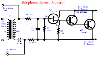
Telephone Record Control
This circuit will allow you to connect any tape recorder that has a mic and remote input to a phone line and automatically record both sides of a conversation when ever the phone is in use.
FM Stereo Transmitter
Hand Clap Electronic Control
We have all seen the commercial on TV .......... CLAP - ON - CLAP - OFF - THE - CLAPPER ............ well here is a circuit that will perform that same function.
Circuit operation is as follows. A single hand clap will be picked up by the electric mic which is coupled through C1 into the op amp IC1. The output of IC1 triggers the 555 IC timer IC2 which is configured as a monostable multivibrater. The trigger pulse is stretched by IC2 and outputs a pulse to IC3 a D type flip flop. Because of the three state counter arrangement of IC3, two sharp claps are required before IC3 will output a high to Q1 which will turn on K1 relay and any device connected to K1's switch contacts. ....Link : Hand Clap Electronic Control
In Circuit Transistor Checker
This simple circuit has helped me out on many occasions. It is able to check transistors, in the circuit, down to 40 ohms across the collector-base or base-emitter junctions. It can also check the output power transistors on amplifier circuits.
Circuit operation is as follows. The 555 timer ( IC1 ) is set up as a 12hz multi vibrator. The output on pin 3 drives the 4027 flip-flop ( IC2). This flip-flop divides the input frequency by two and delivers complementary voltage outputs to pin 15 and 14. The outputs are connected to LED1 and LED2 through the current limiting resistor R3. The LED's are arranged so that when the polarity across the circuit is one way only one LED will light and when the polarity reverses the other LED will light, therefore when no transistor is connected to the tester the LED's will alternately flash. The IC2 outputs are also connected to resistors R4 and R5 with the junction of these two resistors connected to the base of the transistor being tested. With a good transistor connected to the tester, the transistor will turn on and produce a short across the LED pair. If a good NPN transistor is connected then LED1 will flash by itself and if a good PNP transistor is connected then LED2 will flash by itself. If the transistor is open both LED's will flash and if the transistor is shorted then neither LED will flash.
From :: http://home.maine.rr.com/randylinscott/nov97.htm
Saturday, January 27, 2007
Schematic mobile phone #2
Er_S868ru.zip | 860 KB | 26/9/2544 | 0:00:00 |
M35_eng.zip | 473 KB | 26/9/2544 | 0:00:00 |
M35_ru.zip | 1119 KB | 26/9/2544 | 0:00:00 |
Nokia-6260.rar | 524 KB | 1/10/2549 | 8:31:00 |
Nokia-N70.rar | 4575 KB | 1/10/2549 | 8:36:00 |
PhillipsGenie.zip | 18 KB | 26/9/2544 | 0:00:00 |
RemoteSelector.zip | 122 KB | 26/9/2544 | 0:00:00 |
S35_eng.zip | 558 KB | 26/9/2544 | 0:00:00 |
S35_ru.zip | 659 KB | 26/9/2544 | 0:00:00 |
S35i_eng.zip | 633 KB | 26/9/2544 | 0:00:00 |
SGH_2100eng.zip | 466 KB | 26/9/2544 | 0:00:00 |
SGH_2200ru.zip | 1049 KB | 26/9/2544 | 0:00:00 |
SGH_2400eng.zip | 328 KB | 26/9/2544 | 0:00:00 |
SGH_250eng.zip | 954 KB | 26/9/2544 | 0:00:00 |
SGH_600eng.zip | 370 KB | 26/9/2544 | 0:00:00 |
SGH_800eng.zip | 363 KB | 26/9/2544 | 0:00:00 |
SGH_A100ru.zip | 752 KB | 26/9/2544 | 0:00:00 |
ST7797eng.zip | 2949 KB | 26/9/2544 | 0:00:00 |
Sagem922_ru.zip | 43 KB | 26/9/2544 | 0:00:00 |
Siem_WAP_eng.zip | 77 KB | 26/9/2544 | 0:00:00 |
WAPtor_about.doc | 22 KB | 26/9/2544 | 0:00:00 |
Schematic mobile phone #1
1018_eng.zip | 603 KB | 26/9/2544 | 0:00:00 |
5110_ru.zip | 807 KB | 26/9/2544 | 0:00:00 |
607_ru.zip | 48 KB | 26/9/2544 | 0:00:00 |
6150_ru.zip | 2258 KB | 26/9/2544 | 0:00:00 |
768_rus.zip | 870 KB | 26/9/2544 | 0:00:00 |
8110_ru.zip | 16 KB | 26/9/2544 | 0:00:00 |
8810_ru.zip | 1200 KB | 26/9/2544 | 0:00:00 |
C35_eng.zip | 557 KB | 26/9/2544 | 0:00:00 |
C35i_ru.zip | 1119 KB | 26/9/2544 | 0:00:00 |
EngFiOpMenu.zip | 14 KB | 26/9/2544 | 0:00:00 |
Er_A1228d.zip | 975 KB | 26/9/2544 | 0:00:00 |
Er_GA628eng.zip | 648 KB | 26/9/2544 | 0:00:00 |
Er_GF768eng.zip | 647 KB | 26/9/2544 | 0:00:00 |
Er_R280d_ru.zip | 2228 KB | 26/9/2544 | 0:00:00 |
Er_R320s_rus.zip | 1307 KB | 26/9/2544 | 0:00:00 |
2 Cell Lithium Ion Charger
The charger operates by supplying a short current pulse through a series resistor and then monitoring the battery voltage to determine if another pulse is required. The current can be adjusted by changing the series resistor or adjusting the input voltage. When the battery is low, the current pulses are spaced close together so that a somewhat constant current is present. As the batteries reach full charge, the pulses are spaced farther apart and the full charge condition is indicated by the LED blinking at a slower rate.
A TL431, band gap voltage reference (2.5 volts) is used on pin 6 of the comparator so that the comparator output will switch low, triggering the 555 timer when the voltage at pin 7 is less than 2.5 volts. The 555 output turns on the 2 transistors and the batteries charge for about 30 milliseconds. When the charge pulse ends, the battery voltage is measured and divided down by the combination 20K, 8.2K and 620 ohm resistors so that when the battery voltage reaches 8.2 volts, the input at pin 7 of the comparator will rise slightly above 2.5 volts and the circuit will stop charging.
Link : 2 Cell Lithium Ion ChargerFriday, January 26, 2007
CAR BATTERY TESTER
Checking the status of your car battery (accumulator) should be easier with this circuit which measures the internal resistance of the battery. Pulses generated by the 555 are used to drive a dummy load and the AC voltage which develops across the battery gives an indication of its internal resistance: the lower the voltage the healthier the battery. The AC voltage is read out by means of a digital meter connected at the output. Separate leads are used for the dummy load and for the metering circuit. They should be connected to their respective battery lugs but they should not touch each other. This avoids erroneous readings due to less than perfect contacts of the dummy load. The internal resistance depends on the battery temperature as well; this is the reason for the switch: hot means a battery (not ambient) temperature between 35 and 52 degrees Centigrade, normal is for a temperature between 16 and 34 degrees and cold is good for a temperature from -4 to 15. Beyond these ranges the reading is unreliable. The internal resistance depends also on the rated capacity of the battery. The 100 ohm potentiometer sets the battery capacity: it is rotated totally to positive for a 100Ah battery and totally to negative for a 32Ah battery. A dial with uniform markings from 32 to 100 was used in the prototype. This means we can measure internal resistance of batteries rated from 32 to 100Ah. As there are a number of smaller 12V batteries around, specially for alarm systems, a switch was introduced that, in the X1 position, will change the capacity range to 3.2 - 10Ah. The unit has six leads going out of the box: two for the dummy load, two for the metering section and two going to the digital meter. Operation is simple: set the range, temperature and battery rating, then connect the dummy load and the metering leads to the battery lugs and read the ac voltage: you should be safe if it reads below 10-12mV otherwise it is better to give the battery a good recharge and if it is still beyond 10-12mV then probably you need a new battery. A bright orange LED shows that the unit is connected and in operation.
From :: http://digilander.libero.it/bubblegate/eindex.html
ALKALINE CHARGER
This circuit was specifically designed to recharge alkaline cells. The unusual connection of the transistor in each charging unit will cause it to oscillate, on and off, thus transferring the charge accumulated in the capacitor to the cell. The orange LED will blink for around 5 times a second for a 1.37V cell. For a totally discharged cell the blinking is faster but it will decrease until it will come to a stop when the cell is charged. You may leave the cell in the charger as it will trickle charge and keep it at around 1.6V. To set the correct voltage you have to connect a fresh, unused cell and adjust the trimmer until oscillations set in, then go back a little until no oscillation is present and the circuit is ready to operate. You should use only the specified transistors, LED colors, zener voltage and power rating because they will set the final voltage across the cell. A simple 9V charging circuit was also included: it will charge up to around 9.3V and then keep it on a trickle charge: the green LED will be off while charging and will be fully on when the battery is close to its final voltage.
A 2.5VA transformer will easily charge up to 4 cells at the same time although 2 only are shown in the schematic. In order to minimize interference from one circuit to the other they have nothing in common except the transformer and, in order to show a balanced load to the transformer, half of the charging units will use the positive sinewave and the other half the negative sinewave.
All types of alkaline cells can be recharged: it will take 1 day for a discharged AA cell or 9V battery and up to several days for a large D type cell. The best practice is not to discharge completely the cell or battery but rather to give a short charge every so often although admittedly this is not easy to achieve.
I tried successfully to recharge NiMH cells as well. Although the charging profile for these cells is quite different from alkaline cells, the circuit seems to work fine provided you do not leave them in the charger forever, because of the possibility of overcharging especially for the smaller batteries.
The mains transformer must be suited for the voltage available in each country: usually 230Vac or 115Vac.
From :: http://digilander.libero.it/bubblegate/eindex.html